
Thanks to the current economic environment, I find myself with some unexpected time on my hands. The financial manager has decreed spending must be curtailed so I thought I had nothing to lose by trying to fix the tachometer on the ST4S.
People have said that they can be opened and fixed but I couldn’t find any pictures etc after a search so thought I would rectify that situation. It was fiddly but well worth the time spent as (for now at least) it works well.
Symptoms were that the needle was sticking at 7k and not responding at tickover. The first tear down to check it over followed by tightening up the brass screws at the back made it worse as tickover was then showing as 4000 rpm so it was at that point that I thought I had better work out how it works….
First check is that the feed to the tach via the 3-pin connector is working properly. There are two bullet connector feeds for the immobiliser led but this is completely separate to the rev-counter function and only shares the common housing. The grey and black wire on the main connector for the tach is the earth whilst the light blue wire is +12V. These are obviously easy to check. The green wire feed is from the ECU and feeds a square wave signal to the tach electronics and so is harder to check. I managed to borrow an ancient oscilloscope to check the signal and it was a nice clean square wave with a frequency of about a third of the engine rpm (ie about 333 hz at tickover). As expected, the frequency increases proportionally as the engine is revved. Measuring the voltage at the centre pin with a multimeter set to DC gave me about 1 volt less than battery voltage with the ignition on and about 2.5V with the engine running (not changing with rpm) so that may help diagnose for those without oscilloscope.
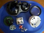
Now confident the wiring was working, I set to with the Dremel and a cut-off disk and split the housing about 1” below the bezel. There is nothing to damage at that level. Removing the 3 brass sleeve nuts at the back then allow the circuit board to be separated from the needle movement. It’s a fairly basic circuit and a bit of research into the IC (CS289) reveals that it is an industry standard air-core tachometer drive circuit. A simple internet search revealed a data-sheet which allowed me to understand the basics. The circuit takes the signal from the incoming square wave and converts it to three DC feeds (corresponding to the 3 connections mediated via the brass sleeve nuts to the meter movement). There is a reference voltage feed Vz along with Vsine and Vcosine feeds. Basically, the meter movement has two sets of windings at 90 degrees apart connected together at the Vz feed. Varying the magnitude of the Vsine and Vcosine voltages forces the needle to a certain degree of rotation. Each meter winding should be about 200 ohms. In my case, a quick check showed only one working winding. Thus, I popped off the needle and unscrewed the dial to allow me to remove the meter movement. It then became clear that when I had tightened one of the brass screws, the whole mounting post had twisted and broke the very fine wire feed from the coil (hopefully clear from the picture). I managed to re-solder the connection and then used Plastech to reinforce the post to (hopefully) prevent it twisting on reassembly. I then reassembled and checked that all is well at the brass connections at the rear (200 ohms across two of the connectors and 400 ohms across the other). The difficulty is now putting the needle back in the right place! My first guess resulted in a working tacho but it was showing a tickover at 2,500 rpm. I suspect they apply a calibrating signal when they build them and then pop the needle on at the appropriate place. I resorted to letting the bike tickover at what was previously a reliable 1000 rpm and then popped the needle back so it read what it did before. Its probably not as accurate as the factory method but will be close enough for normal riding. Now happy it was working again, I used Plastech to ‘glue’ the housing back together again and finished it off with Duck tape. Once mounted back in the dash the repair is invisible. Not sure how long it will last but it kept me quiet for a few hours")
The main message should be that be careful not to tighten up those brass screws too tight or you risk breaking a connection in the meter in the same way I did. They should only be nipped up. If tightening them doesn’t work then get a multimeter and check you have 200 ohms across two of the brass connectors and 400 ohms across the other. If that is OK then you have no need to dismantle the meter movement so check the circuit board for dry joints or fracture. It’s a pretty basic circuit so any electronics repair guru should be able to trouble shoot and fix it.
Hope that helps,
Keith
People have said that they can be opened and fixed but I couldn’t find any pictures etc after a search so thought I would rectify that situation. It was fiddly but well worth the time spent as (for now at least) it works well.
Symptoms were that the needle was sticking at 7k and not responding at tickover. The first tear down to check it over followed by tightening up the brass screws at the back made it worse as tickover was then showing as 4000 rpm so it was at that point that I thought I had better work out how it works….
First check is that the feed to the tach via the 3-pin connector is working properly. There are two bullet connector feeds for the immobiliser led but this is completely separate to the rev-counter function and only shares the common housing. The grey and black wire on the main connector for the tach is the earth whilst the light blue wire is +12V. These are obviously easy to check. The green wire feed is from the ECU and feeds a square wave signal to the tach electronics and so is harder to check. I managed to borrow an ancient oscilloscope to check the signal and it was a nice clean square wave with a frequency of about a third of the engine rpm (ie about 333 hz at tickover). As expected, the frequency increases proportionally as the engine is revved. Measuring the voltage at the centre pin with a multimeter set to DC gave me about 1 volt less than battery voltage with the ignition on and about 2.5V with the engine running (not changing with rpm) so that may help diagnose for those without oscilloscope.
Now confident the wiring was working, I set to with the Dremel and a cut-off disk and split the housing about 1” below the bezel. There is nothing to damage at that level. Removing the 3 brass sleeve nuts at the back then allow the circuit board to be separated from the needle movement. It’s a fairly basic circuit and a bit of research into the IC (CS289) reveals that it is an industry standard air-core tachometer drive circuit. A simple internet search revealed a data-sheet which allowed me to understand the basics. The circuit takes the signal from the incoming square wave and converts it to three DC feeds (corresponding to the 3 connections mediated via the brass sleeve nuts to the meter movement). There is a reference voltage feed Vz along with Vsine and Vcosine feeds. Basically, the meter movement has two sets of windings at 90 degrees apart connected together at the Vz feed. Varying the magnitude of the Vsine and Vcosine voltages forces the needle to a certain degree of rotation. Each meter winding should be about 200 ohms. In my case, a quick check showed only one working winding. Thus, I popped off the needle and unscrewed the dial to allow me to remove the meter movement. It then became clear that when I had tightened one of the brass screws, the whole mounting post had twisted and broke the very fine wire feed from the coil (hopefully clear from the picture). I managed to re-solder the connection and then used Plastech to reinforce the post to (hopefully) prevent it twisting on reassembly. I then reassembled and checked that all is well at the brass connections at the rear (200 ohms across two of the connectors and 400 ohms across the other). The difficulty is now putting the needle back in the right place! My first guess resulted in a working tacho but it was showing a tickover at 2,500 rpm. I suspect they apply a calibrating signal when they build them and then pop the needle on at the appropriate place. I resorted to letting the bike tickover at what was previously a reliable 1000 rpm and then popped the needle back so it read what it did before. Its probably not as accurate as the factory method but will be close enough for normal riding. Now happy it was working again, I used Plastech to ‘glue’ the housing back together again and finished it off with Duck tape. Once mounted back in the dash the repair is invisible. Not sure how long it will last but it kept me quiet for a few hours
The main message should be that be careful not to tighten up those brass screws too tight or you risk breaking a connection in the meter in the same way I did. They should only be nipped up. If tightening them doesn’t work then get a multimeter and check you have 200 ohms across two of the brass connectors and 400 ohms across the other. If that is OK then you have no need to dismantle the meter movement so check the circuit board for dry joints or fracture. It’s a pretty basic circuit so any electronics repair guru should be able to trouble shoot and fix it.
Hope that helps,
Keith