Ducati.ms - The Ultimate Ducati Forum banner

M696 Android Dashboard with Arduino

1 reading
57K views 73 replies 19 participants last post by  arbtin  
#1 ·
I've been working on this project for quite some time now so it's time to share my ideas and thoughts. Last year I was looking for navigation and navigation mounts for my Monster 696. After a long search I came to the conclusion that all mounts will 'break' the esthetics of the bike. The only logical place for a navigation system would be on the dashboard, it even has the size of it. But obviously there's a problem. if you put a navigation system there, it will block of your crucial motor data, like rpm, accurate speed, neutral, etc. mmm

But wait, doesn’t the m696 has DDA port? And can't we read the data from it? Yes we can(bus)!

So I bought an Arduino and a canbus shield and started logging. Based on this post, I thought it should be possible and after some long days of searching I found the answers inside of the enormous datalogs. A matrix of the canbus id's and byte can be found here.

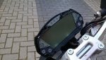
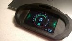
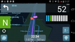
Next is the dashboard itself. Because Android Is the most open platform and has a lot of navigation systems available, it was the obvious choice. I needed a way to display my motor data, and still show the navigation in the background. Luckily, android supports floating Windows on top of other applications, a very first draft of the software looks something like this:
Image


I'm also thinking to create different set of views, that you can switch with the normal buttons on steer, so you can also get a full screen dashboard.


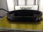
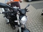
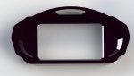
And the last part is maybe the most tricky part. How about the esthetics? Well, there is a solution for that, 3D printing. And that's a completely new world for me. So my first revision looked like this:

Image


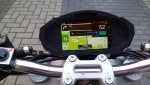
I've designed it in a way that the original dashboard will still be there, without the cover, and an android Motorola phone will fit under it. The original plan was to keep the normal lights for neutral, blink, etc. But as it turns out, there is just not enough space, even if you try to 'guide' the light with plexiglass to a different position.

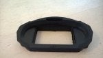
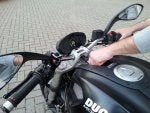
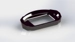
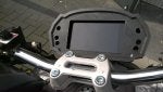
So I needed to find more information on the CANBUS so I could skip the original indicators and a better design. And with a little help, the next design became a lot better:

Image


Image

There is still a lot of work to do, like creating a proper power cable for the Arduino with the right voltage regulators, refactoring a lot code on both Android and Adruino and making a proper fit for the new cover. I'll post the photo's as soon as the next 3d print arrives.
 

Attachments

#2 ·
I can't even begin to understand what you've gone through to get this far, but I am IMPRESSED!!!
Like they say, "necessity is the mother of invention".
Good luck, and seriously look at this as a business!!
Most BMW RT / LT riders would pay top dollar for this feature.
 
#3 ·
Thx jduke, indeed, it's been a hell of journey, there were a lot of days (and nights) where I would call it a day.....

A lot of people are saying that I've should do something commercial with it, so maybe there something into it, currently i'm just doing it for the challenge and fun ;)
 
#7 ·
Awesome! I'm assuming you may run into issues with your immobilizer when trying to integrate this setup?

I burned out my original gauge and had to buy a new one. Still waiting on getting it programmed since the bike won't start.

Very interested in your end product by the way. Looks great.
 
#8 ·
The immobilizer is looking for a certain frequency code from the key (or vise versa...) before it will start. Maybe you could "read" the code and program it into the dash?? Of course that would defeat the security the immobilizer is supposed to give, but I've heard more reports of problems than i have success stories.
As I said in an earlier post, I have no idea what foske went through, but have confidence if it could be done he could do it.
 
#9 ·
Thanks all for the postive feedback! @0612Devil, because of the immobilizer I've chosen not the remove the dashboard, but to put the phone on top of it. I did remove the top plastic cover to create space. But it is an interesting idea to remove the original dash entirely, but at this point, there is no real need for it.
 
#12 · (Edited)
So, I've received the newly printed cover, and I must say, it looks awesome :D

There are a few problems with the design, but that was to be expected:
- The volume button is stuck because we made it to tight, as you can see on the screen
- it's not deep enough to fit properly
- The usb cable doesn't fit in yet, we need to make more room for it.
- The hole for the screen should be aligned slightly better

And the best of it all, we created the back lining just by tracing a picture, and that fits really tight and nicely. (On the picture it's a bit lower because the screws didn't fit).

(the pictures aren't that good... Windows Phone :|)
 

Attachments

#14 ·
Thx Matt360x!

Today I've sketched this full screen interface for when you're not navigating. I was also thinking about some sort of racing mode, but I would like to know from you guys what kind of info you would like to see on it. Any thoughts on that?
some thinks that crossed my mind:
- Lap timing (based om gps coordinates?)
- track map, with your location on it (and even better, your competitors if equipped with the same GPS tracker)
 

Attachments

#15 ·
Hello foske, I wanted to let you know we are working on very similar projects, although I am focusing on a different aspect for the moment. ;)

Please take the following with a grain of salt:
I believe it is possible to disable the immobilizer in the Monster 696 series of ECU, I have seen it advertised by MotoWheels (vendor of Rexxer).
Perhaps you can contact them and discover if the dash can be removed as well.
The dash has some mission-critical sensors such as air pressure that may or may not allow the bike to start if missing.

However, it may be possible to emulate these sensors using your Arduino. ;)
I suggest investigating the traffic immediately when you key the bike on.
I do not have a 696, but with the equipment I have made, it would be possible to investigate further.

For the moment I will continue my original goal, but plan to keep close tabs on your work.
I look forward to your clever solutions to the challenges you enjoy! :D
 
#16 ·
Thx for the advice Impulsive_duc. I'm currently not looking for a way to remove the immobilizer, i like the extra protection it brings ;), but it is a good thing to know that it is possible.

At the moment i'm trying to resolve a conflict between my canbus shield and the usb host shield. I've changed the pins already because both shields are using pin 9 but for some reason at this point, if both shields are operating at the same time, my RPM and speed data is reported as 0x00000000.. Other canbus id's are reporting data normally so I think it is in the software, not the hardware.

I would be very interested to see your library, so if you're for it, post it on github ;) I'll try to do that for this project as well.
 
#17 · (Edited)
What shields and mainboard are you using? If you can give a link to their datasheet page/wiki, that would be better. I am guessing you are using an Arduino with a dedicated SPI header, not the "Arduino Uno R3" pins 10-13 SPI?

(Edit: I re-read your post, you've already addresses the SPI CS pin issue. :) So I have removed duplicate description here.)

You may have to edit the library to access the CS pins by Register instead of DigitalWrite since DigitalWrite function in Arduino is simply too slow. (~120ms toggle?)

Also, are you using the MCP2515's CANbus ID filtering capability or are you listening to all data on the bus and using logic within your Arduino code? As the stock MCP2515 library is coded, it is EXTREMELY inefficient. To read a CAN packet it issues over 5 SPI CS/write/read sequences. I have slimmed down the library to issue only 1 SPI CS/write/read transaction to read a packet. For low-arbitration CANbus IDs with an extremely high frequency such as RPM and Speed, the stock library can easily overwhelm the SPI bus. This is especially true if using Arduinos with a cap at 8Mhz (or even 4MHz!!) SPI prescaler frequency.

I am very interested to know what Arduino device you are using that has such a nice display! I actually do not know how to use GIT. :) Rather, I have not invested the time since I am likely to do something silly like overwrite someone else's code! I am asking CKelley for assistance with that, please PM me where to e-mail what I currently have.
 
#18 ·
PS: I read through your CANbus ID spreadsheet, thank you very much for posting it. :) MrCanBus would be very happy. We need to post all these online, editable in one place, like Google Docs so everyone can contribute. :)

Since I do not want to post conflicting spreadsheets, I will link the EXACT file I am correcting and describe the corrections textually:


Throttle position: You said Byte-0 of PID-0x81 varies between 0x1 and 0xc9. Could this be TPS as (0xc9 >> 1) in {0.0 - 100.0%} using {.5%} increments? This would line up with what I see inside the Siemens firmware...
0xc9 = 201, 0x01 = 1
(201-1) / 2 = 100.0
(1 - 1) / 2 = 0.0​

Engine temp: You list this under PID-0x211 as "Voltage??". But from my experience editing Ducati firmware I can tell you Ducati stores temperatures internally almost universally using "X - 40" conversion. (i.e. 30 DEC in f/w means -10 'C)

Therefore I believe Byte-1 of PID-0x211 is in fact Engine Temp. It makes logical sense since Air Temp is Byte-3.

Voltage: Since this is low-priority information, I believe it would be in a high-arbitration ID. So is likely in PID-0x300. I suspect Byte-1 is Voltage/10 for the same reason you thought it was engine temp.

Dash text: This is stored in PID-0x280 and PID-0x290 as ASCII encoded text. It brings up the possibility of spoofing the welcome message with some clever encoding. :)
 
#25 · (Edited)
SPREADSHEET BEING CORRECTED:

................
Ignore everything I said there. Damn, I wish this forum let you edit technical comments.... :mad:
I ran through your datalogs and updated my spreadsheets to MrCanBus's site. I located (I think):
  • Speed (ABS + ECU, 2 copies -- 1 might be the front wheel encoder for DTC)
  • RPM (ABS + ECU, 2 copies -- may be related to DTC)
  • TPS (2 copies -- 1 may be APS for DTC)
  • Time + Mileage + Dash Text
  • Neutral + (Possible) Sidestand + Run switch + Clutch
  • Engine temp + Air temp
  • Air pressure
  • Voltage
I still need your help logging data. I don't even own one of these. :p
A lot of the above are just educated guesses. Very educated guesses, but guesses nonetheless.
 
#20 · (Edited)
Yeah we should setup a central Excel matrix for sure, I'll try to test out your remarks and add them to the matrix. Maybe the slow SPI bus is the reason i some see some contradicting messages...

for the record, i'm currently using this setup:
- Arduino Uno R3
- Seed studio canbus
- Keyes host shield
- buck converter (to bypass the internal regulator to supply power if no laptop is attached)

And thanks for the offer Goayala, it's definitely something I'm thinking about, maybe for in the future if the prototype had it's first run :)
 
#21 ·
Image


Oh wow.

A few immediate thoughts:
» Wow this is epic.
» Instead of Arduino, you'll want to use a ChipKit since those can actually work fast enough to make acceptable graphics. Plus there's a framebuffer library for it.
» You can use resins and molds to easily make the final dashboard. What's great is that you can sand and finish a 3D printed part and that now-perfect finish will become the master part.
» We need something like GitHub, but for code, CAD drawings, and documents. (I hate github, too, it's too hard to set up work flows)
» Once the software and electronics requirements are finalized, we'll figure out the lowest price hardware that can run it. We probably won't need a custom PCB made, since the crucial restraint will be the display.

On the software for the screen:
» If each function were to be made into modules, it could be easy for the user (person riding the bike) to add and remove functions.

And in case you didn't notice... WOW!
Chris
 
#22 ·
foske, this is impressive work. I strapped my iPhone 6+ over my dash during a track day to run Harry's Timer in conjunction with a Vbox Sport for timing and realized how lacking the displays are on most bikes. I'll be watching your thread with interest.

Out of curiosity, do you know how to trick the light sensor into thinking it's always dark? I'm guessing it's a matter of covering up the sensor but I'm not sure if it's accessible within the display. I find the recessed display on my '12 M1100 difficult to read. That would be a small victory if the display were easier to read.
 
#23 ·
Thx Chris, just a quick response to your suggestions:
The main focus of this project was adding navigation, and there are a lot of good navigation software out there on Android. So I would like to stick with Android for that part. So the only thing that the Arduino is doing, is forwarding the canbus messages, graphics are handled by Android. Currently I'm using a Motorola G right know, but it's definitely an overkill. The Chipkit sounds interesting. Do you know any projects that run navigation software on the Chipkit?

The resins and molds suggestion sounds interesting, i'll check it out.

For the software, at this point a created a Android service, that broadcasts the data. So adding screens or functionality is relatively easy. (Even for different apps I believe)
I would like the use the hardware buttons on the handlebar to switch between screens. So I ordered a couple of opto couplers to hook up to the electrical system, because I don't believe there on the bus. Just as the indicators.

@quito: Thx! I didn't had the change (courage) to write data back. I think that the sensor and back light are a closed circuit inside the dashboard, but I don't know for sure.
 
#27 ·
Thx Chris, just a quick response to your suggestions:
The main focus of this project was adding navigation, and there are a lot of good navigation software out there on Android. So I would like to stick with Android for that part. So the only thing that the Arduino is doing, is forwarding the canbus messages, graphics are handled by Android. Currently I'm using a Motorola G right know, but it's definitely an overkill. The Chipkit sounds interesting. Do you know any projects that run navigation software on the Chipkit?

The resins and molds suggestion sounds interesting, i'll check it out.
Ah, navigation, right. THAT will be on Android... but now I need to wrap my mind around the concept of how to blend an MCU (chipKIT, arduino, etc) with it. Because if the coding for Android is generic enough, that takes the GUI work out of the embedded platform...

Chris
 
#24 ·
Yep, interesting stuff. :) Although he is running into the same CAN problems we did or the datalogger. I gave foske my optimized libraries to try fixing some data corruption errors. (I ended up GPLing the libs since as far as I know, nobody else has coded the silicon fix for the MCP2515 controller.) All roads lead to Rome. :p

We need to kick these projects into gear. Many have been languishing for years simply because all the info was too spread out. foske still needs to verify his PID assignments, and I'm asking MrCanBus is he will host the master spreadsheet. I need raw can dumps to help him, though... valid, clearly documented ones.

Do you think you can volunteer CannedIce's bike as a test mule? I can send you the plugs you need to plug the ChipKit logger into the harness, and the code to log to SD (once I port MrCanBus's one).
 
#26 ·
I've been working a lot on fine tuning the project on all fronts. 3d, Arduino and Android. A lot of help came from Impulsive_duc, so a really big thanks for that! We made good progress on identifying the data that is on CANBUS, https://docs.google.com/spreadsheet...dsheets/d/1-NJ9OlGQYTGMzBzwDPYn-aI_7_ign9SCiscKZufx3Uw/edit?pli=1#gid=813963652 and it's very cool to see that the gear indicator is already on the BUS. But we are missing some semi important stuff like indicators and fuel indicator.
I also got my new 3D printed revision from the local printing shop, FabLab Breda and it all fits really well, even the screw holes are an exact match! :surprise:

And to top it off, a small movie that shows the "racing" interface with a running engine:
http://1drv.ms/1GS17nI

The next step is of course some bug fixing, but also I need to tackle the electronics so I can take it for a spin :grin2:
 

Attachments

#28 ·
I'm currently using the USB-Can Pro v5.0 protocol, implemented in Arduino by Impulsive_duc. The Android part is reading this byte stream. I already created a simulator that uses records files instead of the USB connection, that eases the Android developement a lot. Creating a BT connection would be very easy to implement as well. I think this is be a great way to decouple the system. It does need a way to talk back to the arduino though, because at this point it is one way only..